Removing and Installing Constant Velocity Joints
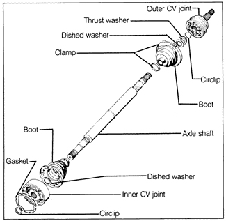
Fig. 5-4 is an exploded view of a drive axle and its two constant velocity joints. Notice the ridges that are forged into the shaft for the purpose of holding the rubber boots in place. New circlips should be used when reinstalling the joints, and new clamps should be used to fasten the boots.
NOTE-
Because the CV joints must be removed to replace the boots, it is good preventive maintenance to replace the boots whenever the CV joints are removed.
|
| Fig. 5-4. | Drive axle assembly showing inner and outer constant velocity joints and attachment parts. |
|
To remove and install the CV joints, it is necessary to first remove the drive axles as described above. CV joints are not rebuildable, and must be replaced as complete units. Volkswagen specifies a special molybdenum disulfide grease for packing CV joints. See LUBRICATION AND MAINTENANCE for more information on CV joint lubricant. Some special tools and equipment are required to remove and install CV joints. Read the procedure carefully before starting work. If you lack the necessary tools and equipment, or a suitable workplace, we suggest leaving these repairs to an authorized Volkswagen dealer or other qualified repair shop.
To remove and install outer CV joint:
| 1. | Cut and remove the large clamp holding the rubber boot to the CV joint. Fold the boot back from the joint, inside out over the shaft. |
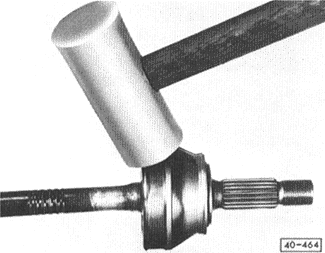
| 2. | Clamp the shaft in a vise, and drive the joint off the shaft, as shown in Fig. 5-5, using a soft-faced mallet. Remove the thrust washer, the dished washer, and the circlip from the axle and inspect the shaft for wear. |
NOTE-
The CV joint is secured to the shaft with a circlip that is inaccessible. The force used to drive the joint off the shaft must be sufficient to override the clip, but not enough to cause damage to the joint.
|
| Fig. 5-5. | Outer CV joint being driven off axle shaft with soft-faced mallet (shown with boot removed for clarity). |
|
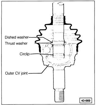
| 3. | When installing the joint, use a new circlip in the groove at the end of the axle shaft. See Fig. 5-6. Drive the joint onto the shaft until the circlip is seated. Fold the boot back over the joint, using a new clamp to hold it. |
| Fig. 5-6. | Cutaway view of outer CV joint, showing positions of circlip and washers. |
|
To remove and install inner CV joint:
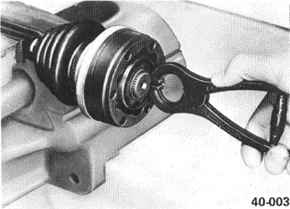
| 1. | Remove the circlip from the end of the axle shaft, as shown in Fig. 5-7. |
| Fig. 5-7. | Removing circlip which holds inner CV joint to axle shaft. |
|
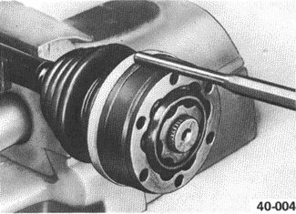
| 2. | Drive the protective cap off of the outer ring of the joint, as shown in Fig. 5-8, and fold the boot away from the joint, inside out over the axle shaft. |
CAUTION-
Do not pivot the ball hub more than 20° in the outer ring of the joint. The balls will fall out if the hub is pivoted too far.
|
| Fig. 5-8. | Driving off CV joint protective cap with drift and hammer. |
|
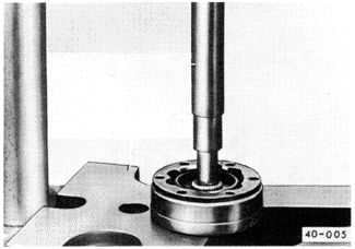
| 3. | Support the hub of the CV joint and press the axle shaft out of the joint, as shown in Fig. 5-9. |
| 4. | Remove the dished washer and inspect the shaft and the splines for wear and damage. |
| Fig. 5-9. | Driving axle shaft out of inner CV joint with punch (drift) and thrust plate (support). |
|
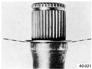
| 5. | When installing the CV joint, use a new dished washer and install it with the concave surface facing the end of the shaft, as shown in Fig. 5-10. |
| Fig. 5-10. | Correct installation of dished washer used with inner CV joint on end of drive axle. |
|
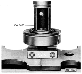
| 6. | Press the joint onto the shaft as shown in Fig. 5-11. While using the press to hold the hub of the CV joint against the dished washer, install the circlip in the groove on the end of the shaft. |
| Fig. 5-11. | Pressing inner CV joint onto drive axle shaft. Press tool shown, Volkswagen special tool no. VW 522 (order no. TV0 522 000 00 ZEL), allows installation of circlip while CV joint and washer are being pressed. |
|
| 7. | Release the press and make sure that the circlip is completely seated in the groove. Install the protective cap around the edge of the CV joint. |
|


