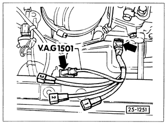
Air Flow Sensor PotentiometerOn CIS-E Motronic systems, the air flow sensor plate potentiometer provides an engine load signal to the control unit for control of ignition timing, acceleration and full-throttle enrichment, and several other functions. The potentiometer's operation can be checked by measuring its output for a given voltage input. Fig. 6-46 shows a special test harness connected to the potentiometer for this purpose.

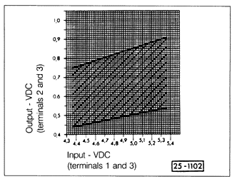
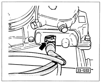
To test, first measure the supply voltage between terminals 1 and 3 with the ignition on. It should be 4.35 to 5.35 VDC. If not, then either the wiring to the control unit or the control unit itself is faulty. Next, switch off the ignition and connect the voltmeter to terminals 2 and 3. Start the engine and let it idle for at least 2 minutes. The voltage measured between terminals 2 and 3 should be within the range specified by the graph in Fig. 6-47, according to the exact supply voltage measured earlier. If the output value does not fall within the range specified in Fig. 6-47, it can be adjusted. The potentiometer is equipped with a small trim screw, located on the side near the harness connector as shown in Fig. 6-48. To adjust, remove the sealing compound covering the screw, rotate the trim screw as required so that output voltage falls within the specified range, then reseal the screw with silicone sealer. If the potentiometer cannot be adequately adjusted by this method, the complete air flow sensor assembly (with potentiometer) should be replaced.


|