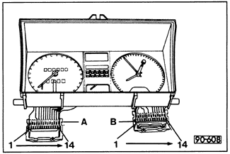
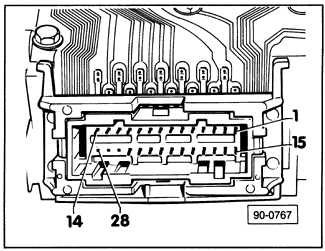
Testing and Replacing Light Emitting Diodes \(LEDs\) and Indicator BulbsTest LEDs and indicator bulbs with the instrument cluster removed and the wiring harness connectors disconnected. Use an external 12-volt power source and jumper wires to apply current to the appropriate terminal in the wire terminal housing. See Fig. 7-3 or Fig. 7-4 and CURRENT FLOW DIAGRAMS for terminal pin identification. If the LEDs or bulbs do not light, check the printed circuit for continuity from the wire terminal housing to the LED or bulb. No continuity indicates that the printed circuit is faulty and should be replaced. If there is continuity, replace the LED or bulb.


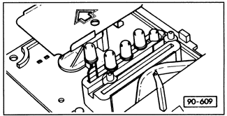
To replace LEDs or indicator bulbs, the instrument cluster must be partially disassembled. Remove the voltage stabilizer as described above, and remove the flexible printed circuit and the LED/bulb holder. Pull the LED or bulb from its holder as shown in Fig. 7-5. When installing new LEDs, take care not to reverse their polarity. The negative (-) terminal of the LED is either slightly wider than the positive (+) terminal, or is indicated by a flat area on the diode housing.

|