3.3 Basic Electrical Troubleshooting Principles
Four things are required for current to flow in any electrical circuit: a voltage source, wires or connections to transport the voltage, a consumer or device that uses the electricity, and a connection to ground. Most problems can be found using only a relatively inexpensive multimeter (volt/ohm/amp meter) to check for voltage supply, for breaks in the wiring (infinite resistance or no continuity), or for a path to ground that completes the circuit in addition, test leads with flat male connectors are needed to prevent damaging terminal connections. For information on using a multimeter or constructing test leads, see FUNDAMENTALS at the front of the manual.
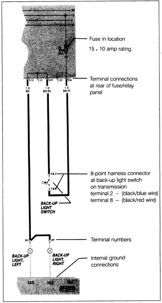
Electric current is logical in its flow, always moving from the voltage source toward ground. Keeping this in mind, electrical faults can be located through a process of elimination. Fig. 3-3 is used to illustrate the logic used in locating a sample fault: back-up lights which do not light.
To troubleshoot a circuit:
| 1. | Check to see that all the connections in the circuit are tight and free of corrosion. Especially make sure that all ground connections are clean, dry, tight, and corrosion-free. |
| 2. | Check the fuse. In the circuit example shown in Fig. 3-3, the circuit receives power through fuse 15. Fuse and relay locations are given in 13. Fuse/Relay Panel. A fuse that repeatedly fails indicates an unusually high current flow, probably caused by a damaged wire, a faulty component, or a short directly to ground. |
| 3. | Check for voltage reaching the circuit. Connect a voltmeter or test light between a point in the circuit and ground (a clean, unpainted metal part of the car). In the example, the ignition must be switched on since fuse 15 only receives power when the ignition is on. See 3.1 How To Read Volkswagen Current Flow Diagrams. |
| Fig. 3-3. | Sample current flow diagram. See procedure To troubleshoot a circuit for example of troubleshooting a circuit. |

|
| 4. | Pick a point where the diagram indicates that there should be voltage. In the example, the terminals "RF" at the connection to the back-up lights should be getting voltage when the ignition is on and the transmission is in reverse. Voltage indicated by the voltmeter (or by the test light lighting up) means that the circuit is doing its job at least as far as that point. |
| 5. | If there is no indication of voltage, something has interrupted the circuit between the power source and the test point. Pick a new test point farther "upstream" in the current path. In the example, terminal T8/8 at the back-up light switch would be a good point. If there is voltage at this point, then the fault lies somewhere between the two test points. |
| 6. | Check circuit integrity between two points with a continuity test using an ohmmeter to measure resistance between the two points. Continuity (little or no resistance) between two points indicates that that part of the circuit is complete and would allow current flow. No continuity (infinite resistance) indicates that part of the circuit is interrupted and would not allow current flow. In the example, operation of the back-up light switch could be checked by disconnecting the harness connector from the switch and testing for continuity across terminals 2 and 8. There should be continuity only when in reverse gear-otherwise the switch is faulty and should be replaced. |
|
